Limited-Time Offer: Enjoy 50% Savings! Ends in 00h 00m 00s Coupon code: 50OFF
Skip to content

Free Autodesk Certified Professional in AutoCAD for Design and Drafting ACP-01101 Exam Questions

Page: 1 / 10 Total 97 questions

Want more questions? Get Premium Access.

Question 1

Tors project area to be completely visible on a sheet, a custom drawing scale of 1: 120 is added to the drawing

After the drawing content is positioned in the viewport using the new drawing scale for the viewport's annotation and standard scales, all annotative objects m the viewport disappear.

No changes are made to the layers within the viewport

What should be done to make the annotative objects visible in the newly scaled viewport?

Correct Answer: C. Add the 1-120 scale to annotative objects in model space.
Explanation:

Understanding Annotative Objects:

Annotative objects in AutoCAD are designed to automatically adjust their size based on the viewport scale to ensure readability.

Issue with Custom Drawing Scale:

When a new custom scale (1:120) is applied, annotative objects disappear if they are not configured to support the new scale.

Options to Resolve the Issue:

Option A: Turning off the annotation monitor within the viewport does not resolve scale issues.

Option B: Moving objects to a new layer does not affect their annotative properties.

Option D: Setting multiple scale positions is a partial solution but does not directly address the missing scale.

Correct Solution:

Option C: Adding the 1:120 scale to the annotative objects in model space ensures that these objects recognize and adjust to the new scale within the viewport.

Steps to Add Scale:

Select annotative objects in model space.

Right-click and choose 'Annotative Object Scale' from the context menu.

Add the new scale (1:120) to ensure objects appear correctly in the viewport.


AutoCAD Help Documentation on Annotative Objects and Scaling.

AutoCAD 2024 User Guide on Managing Annotative Properties.
Question 2

While working in a drawing AutoCAD unexpectedly closes After restarting AutoCAD, the Drawing Recovery Manager palette appears on the screen it shows the drawing tile that was opened in the backup flies list.

Which process should be used within the Drawing Recovery Manager to determine which available file is the most current? (Note. Mac commands shown in parentheses.]

Correct Answer: C. Select each file name and review the last saved date and time in the Details panel.
Explanation:

To determine the most current file in the Drawing Recovery Manager, you should review the last saved date and time for each file in the Details panel. This ensures you are selecting the most recent version of the drawing.

Select each file name:

Procedure: Click on each file name in the Drawing Recovery Manager.

Review the Details panel:

Information: The Details panel provides the last saved date and time for each file.

Purpose: Helps you identify which backup file is the most recent and thus the best candidate for recovery.


Question 3

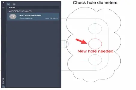
Exhibit.

A CAD designer receives a drawing with an existing trace and update it by adding the new hole as indicated by the arrow in the exhibit.

What displays in the Traces palette after the CAD designer adds their information to the existing trace?

Correct Answer: A. Another contributor in the existing Trace In the palette.
Explanation:

Understanding Traces:

Traces in AutoCAD allow multiple users to collaborate on a drawing by adding comments and updates.

Each Trace keeps a history of contributions and modifications made by different users.

Adding Information to Existing Trace:

When a CAD designer updates a drawing by adding a new hole, this action is recorded in the existing Trace.

The Trace palette will show contributors and modifications, maintaining a detailed record.

Expected Result:

After adding the new hole, the existing Trace will be updated to show another contributor.

This helps in tracking changes and identifying who made specific updates.

Conclusion:

The Traces palette will display another contributor in the existing Trace after the update.


AutoCAD User Guide on Using Traces.

AutoCAD Help Documentation on Collaboration Tools.

Question 4

[Note: The Mac version Is shown in parentheses.]

The ETRANSMIT command Is used to send a package of drawings to a client. The client now states that every drawing file that 15 opened is looking tor SHX tiles that they do not have

How should the Transmittal Setup (Package Drawing) dialog he modified to include the missing SHX files'?

Correct Answer: C. include fonts
Explanation:

Open ETRANSMIT Command: Type ETRANSMIT in the command line and press Enter to open the Create Transmittal dialog box.

Open Transmittal Setup: Click on the Transmittal Setup button to modify the settings.

Modify Transmittal Setup: In the Transmittal Setup dialog box, make sure to select the option Include fonts to ensure SHX files (fonts) are included in the transmittal package.

Save Changes: Click OK to save the settings and then create the transmittal package. This will ensure that all necessary SHX files are included with the drawings sent to the client.


AutoCAD Help Documentation on ETRANSMIT Command

Question 5

You are setting up a drawing layout.

You need to rotate the viewport viewing angle by 90 degrees without rotating the viewport.

What should you do next?

Correct Answer: B. Activate the viewport that you want to rotate. Start the Dview command and use the Twist option.
Explanation:

you need to activate the viewport that you want to rotate and start the Dview command with the Twist option. This will allow you to rotate the view within a viewport without rotating the viewport itself.

https://knowledge.autodesk.com/support/autocad/learn-explore/caas/CloudHelp/cloudhelp/2020/ENU/AutoCAD-Core/files/GUID-D077CEA3-6EC1-4677-BD4B-372D7364D545-htm.html


Question 6

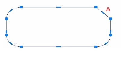
Exhibit.

ACAD designer is modifying the closed polyline using grips.

The top right segment (A) was originally an arc. but is now a chamfered comer.

Which one editing combination did the designer use to make this change? (Note; Mac commands shown in parentheses.

Correct Answer: B. Hover over the midpoint grip and choose Convert to Line

Question 7

You have a line segment that is 150 units long as shown in the exhibit.

You need the line to be 200 units long without adding any additional linework. The leftmost end of the line must remain in the current position.

What should you do?

Question 8

You have the drawing shown in the exhibit.

You need to place the polygon and the rectangle on the same layer as the circle.

Which command should you use to complete the task in the least number of steps?

Correct Answer: A. Match Properties
Explanation:

match properties is a command that allows you to apply the properties of one object to another object. You can use this command to change the layer of an object by selecting an object on the desired layer as a source.

To use this command, you can either:

Click on the Match Properties icon in the Properties panel of the Home tab.

Type MATCHPROP at the command prompt and press Enter.

Then, you can follow these steps:

Select an object on the same layer as the circle as a source object and press Enter.

Select the polygon and the rectangle as destination objects and press Enter.

Now you have placed the polygon and the rectangle on the same layer as the circle.


Question 9

The exhibit shows a workstation arrangement, with horizontal and vertical dimensions, representing the row and column spacings.

Both dimensions have been placed incorrectly, with one origin point of each dimension being placed in the wrong position.

What command should be used to ensure that the dimension objects are placed accurately?

Question 10

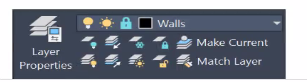
Refer to exhibit.

(Note Exhibit shown is the AutoCAD interlace in Windows White the AutoCAD tor Mac version differs in appearance, the correct answers correlate in the options]

Tim Walls layer is locked in the drawing (see exhibit) and is the current drafting layer

A CAD designer wants to make sure the Walls layer is not visible in the drawing while drafting

Which layer property should the designer set?

Correct Answer: D. Layer Off
Explanation:

To ensure that the 'Walls' layer is not visible while drafting, the appropriate property to set is 'Layer Off.' This will make the entire layer invisible in the drawing.

Layer Off:

Effect: Turns off the visibility of the layer in the drawing, making it not visible.

Usage: This is useful when you want to hide certain elements temporarily without affecting the actual data or properties of the elements on that layer.

Layer Freeze:

Effect: Similar to 'Layer Off,' but additionally, it removes the layer from memory, which can improve performance in large drawings. However, 'Layer Freeze' is not the primary choice when only visibility control is needed.

Layer Lock:

Effect: Prevents editing of the layer's content but does not hide it from view.

Usage: Useful when you want to protect the layer's content from accidental modifications.

Layer Unlock:

Effect: Opposite of 'Layer Lock,' allows editing of the layer's content.