Limited-Time Offer: Enjoy 50% Savings! Ends in 00h 00m 00s Coupon code: 50OFF
Skip to content

Free Autodesk Certified Professional in Revit for Electrical Design RVT_ELEC_01101 Exam Questions

Page: 1 / 7 Total 63 questions

Want more questions? Get Premium Access.

Question 1

Refer to exhibit.

(The image is presented in Imperial units: 1 In = 25 mm [Metric units rounded].)
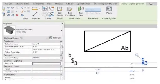
An electrical designer is trying to add the selected three-way switch to the existing switch system "b". The designer is unable to add the switch to the switch system.

Why is this problem occurring?

Correct Answer: B. The switch's Switch ID parameter does not match the switch system.
Explanation:

In Autodesk Revit Electrical Design, lighting control systems such as single-pole, three-way, and four-way switches are managed using Switch Systems. These systems logically connect lighting devices (switches) to the lighting fixtures they control. For multiple switches (like three-way configurations) to be part of the same control circuit, they must share the same Switch ID value.

In the exhibit, the electrical designer is attempting to add a three-way switch to the existing switch system labeled ''b'', but Revit does not allow it. The reason is that the Switch ID parameter of the new switch does not match the Switch ID of the system it is intended to join.

The Switch ID acts as the unique identifier that links all switches controlling the same group of fixtures. If the IDs differ (for example, ''b3'' versus ''b''), Revit interprets them as belonging to separate systems and prevents them from being grouped together.

The Autodesk Revit MEP User's Guide -- Electrical Systems: Lighting and Switch Systems explains this clearly:

''Switch systems are organized by Switch ID. All switches controlling the same lighting circuit must have identical Switch ID values. Revit will not allow a switch to be added to an existing system if its Switch ID does not match that system's identifier.''

To fix this, the designer must: 1 Select the three-way switch. 2 In the Properties palette, locate the Switch ID parameter. 3 Change its value to match the target switch system's ID (in this case, ''b'').

Once both switches share the same Switch ID, Revit will successfully include them in the same Switch System.
Question 2

Refer to exhibit.

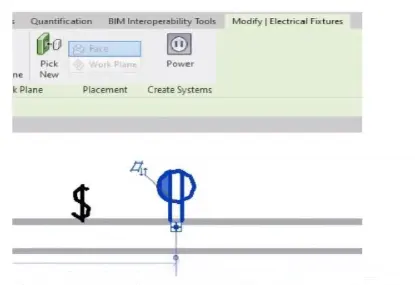
An electrical designer is circuiting a dwelling unit. The receptacle (electrical fixture) shown must be controlled by the switch (lighting device) shown to switch a plug-in lamp When the receptacle is selected, Revit does not provide an option to add the receptacle to a switch system.

What is causing this issue?

Correct Answer: B. The receptacle's 'Switchable' option Is not selected within the family editor.
Explanation:

In Autodesk Revit Electrical Design, when an electrical designer attempts to control a receptacle (an Electrical Fixture family) with a switch (a Lighting Device family) as part of a switch system, Revit will only allow this connection if the receptacle's family has been configured as Switchable within the Family Editor.

According to the Autodesk Revit MEP User's Guide (Chapter 17 -- ''Electrical Systems''):

''Revit allows you to add elements such as lighting fixtures or receptacles to a switch system only if the family includes a switchable connector. The 'Switchable' parameter must be enabled in the Family Editor to allow this connection.''

This means that for the receptacle shown in the exhibit to appear as an available component for switching, the Electrical Connector within its family must have the Switchable property checked. This parameter is found under: Family Editor Select Connector Properties Palette Electrical - Data Switchable.

If this option is not enabled, Revit treats the receptacle as a standard unswitched outlet and will not display it in the switch system creation dialog. Once the option is checked, the designer can reload the family into the project and associate it with a switch system normally.

Additionally, the Smithsonian Facilities Revit Template User's Guide explains this concept as follows:

''To associate receptacles with lighting switches, ensure that the receptacle family has a switchable connector. Without this setting, the device will not appear as an assignable component to a switch system.''

This distinction is important in residential electrical modeling, where switched receptacles are common for plug-in lamps. Lighting circuits can include both Lighting Fixtures and Switchable Receptacles when the family configuration supports it.

Incorrect Options Explanation:

A . A switch system not being created is irrelevant --- the issue occurs before system creation.

C . Being on the same circuit doesn't affect switchability; it affects electrical load connection.

D . Incorrect --- Revit supports switchable receptacles if properly configured.

Therefore, the correct answer is B. The receptacle's ''Switchable'' option is not selected within the family editor.

References:

Autodesk Revit MEP User's Guide -- Chapter 17 ''Electrical Systems,'' pp. 417--421

Autodesk Revit Electrical Design Essentials -- Section ''Creating and Editing Electrical Fixtures and Switch Systems''

Smithsonian Facilities Revit Template User's Guide -- Section 8.4 ''Switchable Receptacle Family Standards,'' p. 89


Question 3

Refer to exhibit.

Correct Answer: A. Select the callout and choose a detail view under Reference Other View.
Explanation:

In Autodesk Revit, when an electrical designer creates a callout view, the software automatically generates a new dependent or independent view based on the selected callout type. However, if a callout is accidentally linked to the wrong or redundant view, the designer can easily reassign it to another existing view without recreating the callout. This can be done using the Reference Other View property in the Properties palette.

According to the Revit MEP User's Guide (Chapter 47 ''Views and Callouts''):

''To link a callout to an existing view rather than creating a new one, select the callout, and under the properties for that element, use Reference Other View to specify the desired target view.''

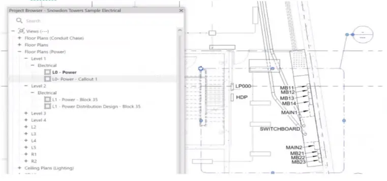
This means that when the designer selects the callout (in this case, shown as ''L0 - Power - Callout 1'' in the Project Browser), they can modify the Reference Other View setting from the Properties palette to point to a different, pre-existing detail view or callout view---for example, one showing an enlarged power distribution layout or switchboard detail.

This is the most efficient workflow because:

It avoids recreating or redrawing the callout (unlike Option C).

It preserves all annotation and sheet referencing data.

It ensures alignment and consistency across sheet references.

The Smithsonian Facilities Revit Template User's Guide reinforces this standard Revit practice:

''When a view reference or callout is incorrectly associated, use the Reference Other View property to redirect the annotation to an existing detail or dependent view.''

Why the Other Options Are Incorrect:

B . Change its type from the Type Selector: Callout types control annotation style (not the referenced view).

C . Delete and recreate: This is unnecessary and inefficient.

D . Open the callout view and change its type: Callout type cannot be changed directly once created; it's controlled by view properties.

Therefore, the correct and Revit-recommended approach is Option A: Select the callout and choose a detail view under Reference Other View.

References:

Autodesk Revit MEP User's Guide -- Chapter 47 ''Views and Callouts,'' pp. 1092--1097

Smithsonian Facilities Revit Template User's Guide -- Section 2.8.1 ''View Types and Templates,'' pp. 29--31

Autodesk Revit Electrical Design Essentials -- ''Callouts, Detail Views, and Referencing Workflows''


Question 4

Refer to exhibit.

(The image is presented in Imperial units: 1 In = 25 mm (Metric units rounded).)

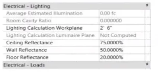
In the space properties for the space, the Lighting Calculation Luminaire Plane is Not Computed. What is causing this issue?

Correct Answer: B. No lights are placed in the space.
Explanation:

The parameter ''Lighting Calculation Luminaire Plane: Not Computed'' in the Space Properties dialog appears when Revit cannot perform a lighting calculation because no valid lighting fixtures are present within that defined space.

According to the Autodesk Revit MEP User's Guide (Chapter: Spaces and Lighting Analysis):

''Lighting calculations are performed based on the luminaire data available in the space. If no light fixtures are present, the parameter 'Lighting Calculation Luminaire Plane' displays as 'Not Computed'. Revit requires at least one hosted or ceiling-mounted lighting fixture with a valid light source to calculate illumination.''

In this case, although the space has defined reflectance values (ceiling, wall, and floor) and a lighting calculation workplane height (2'-6''), Revit cannot compute the Luminaire Plane because the software has no lighting geometry to reference for the photometric analysis.

Explanation of incorrect options:

A . Missing IES file: This would cause inaccurate photometric output, but not ''Not Computed.''

C . Lights not circuited: Circuiting affects load summaries, not lighting calculations.

D . Lights at different elevations: Revit still computes the average luminaire plane even with varied fixture heights.

Thus, the lighting calculation is not computed simply because no lighting fixtures are placed in the space.

References:

Autodesk Revit MEP 2011 User's Guide, Chapter 46: Spaces and Lighting Analysis, pp. 1064--1068.

Autodesk Revit 2021 Electrical Design Guide, Lighting Analysis Parameters.

Smithsonian Facilities Revit Template User's Guide (2021), Section 8.7 -- Lighting Performance Parameters in Spaces.


Question 5

An electrical designer is working on a project with multiple buildings. The designer wants to organize the Project Browser by building For example, all views related to Building A will be sorted under Building A. and all views related to Building B will be sorted under Building B.

The designer decides to create a new parameter, assign it to views, and then sort the Project Browser according to the new parameter.

Which parameter should the designer use?

Correct Answer: C. A project parameter
Explanation:

In Autodesk Revit, Project Parameters are used to add custom fields that apply to multiple elements within a specific project file --- such as views, sheets, or schedules. These parameters allow project teams to categorize, group, and sort information within the Project Browser or within schedules without editing families or external files.

As defined in the Revit MEP User's Guide and Revit Structure Parameters Chapter:

''Project parameters are specific to a single project file. Information stored in project parameters cannot be shared with other projects. A project parameter can be used, for example, to categorize views within a project.''

This statement directly confirms that project parameters are the correct tool for sorting or grouping views in the Project Browser. To organize elements (like views or sheets) by building, the designer can create a custom project parameter named ''Building'' and assign it to the View category. Once assigned, the parameter values (e.g., ''Building A'' or ''Building B'') can be filled in for each view.

The Smithsonian Facilities Revit Template Guide further supports this:

''View purpose is a Revit project parameter, providing a means for users to organize the many views that may exist in a BIM.''

Thus, using a project parameter allows users to add a ''Building'' field to each view, enabling customized browser organization (e.g., group views by Building A, Building B, etc.) without requiring shared parameters or family editing.

References:

Revit MEP User's Guide -- Chapter ''Parameters'' p. 1541--1543

Smithsonian Facilities Revit Template User's Guide -- Section 2.8.1 ''View Types and View Templates,'' p. 29

Autodesk Revit Electrical Design Essentials -- Parameter Management Section


Question 6

An electrical designer wants to add a parameter to a lighting fixture schedule without editing the families. Which parameter type should the designer use?

Correct Answer: B. Project parameter
Explanation:

In Revit Electrical Design workflows, when a designer wishes to add a parameter to a lighting fixture schedule without editing the families themselves, the proper approach is to use a Project Parameter.

The Revit MEP documentation clearly explains:

''To add a custom field to a schedule, you can create a custom parameter using the Parameter Properties dialog. Under Parameter Type, select Project parameter.''

This method links the parameter directly to the project and to all instances of the specified category (in this case, Lighting Fixtures), allowing it to appear in the schedule automatically without requiring any modification to the family files (.RFA).

In contrast:

Family Parameters apply only within the family file and are not schedulable across multiple families.

Global Parameters control dimensional or relational constraints, not schedule data.

Reporting Parameters are read-only and extract model information; they cannot be manually added to schedules.

Revit's scheduling workflow defines this process:

''On the Fields tab of the Sheet List Properties dialog, click Add Parameter... Under Parameter Type, select Project parameter.''

This same mechanism applies to lighting fixture schedules, as schedules and sheet lists share parameter structures in Revit. The new project parameter can then be sorted, filtered, and displayed in the schedule view for documentation or tagging purposes.

References:

Autodesk Revit MEP User's Guide -- Chapter 49 ''Preparing Construction Documents,'' pp. 1126--1128

Autodesk Revit Parameters Overview -- ''Project Parameters'' and ''Shared Parameters,'' pp. 1541--1543

Autodesk Revit Electrical Design Essentials -- Schedule and Parameter Management Section


Question 7

An electrical designer is working in a workshared project with a team of people. The electrical designer does not want to see the linked architectural model in any of their views. The rest of the team still needs to see the architectural link.

Which process should the electrical designer use?

Correct Answer: A. Manage Links > Select architectural link > Click Unload for me
Explanation:

In Autodesk Revit workshared projects, it is common for teams from multiple disciplines (architecture, structure, MEP) to collaborate using linked Revit models. Sometimes, an electrical designer may wish to hide or unload the linked architectural model only for their local session, without affecting how other team members see it.

Revit provides the ''Unload for Me'' option specifically for this purpose.

According to the Autodesk Revit MEP User's Guide (Chapter: Worksharing -- Managing Linked Models):

''When working in a shared model environment, you can unload a link temporarily from your local file using the Unload for Me command in the Manage Links dialog. This action affects only your local copy and does not impact other users working on the project. The link remains loaded for all other team members.''

This means that using Manage Links Select the architectural link Click Unload for Me, the designer can remove the visual presence of the architectural model from all of their views without impacting the rest of the team. The link remains active in the central model, and other disciplines will continue to see it as usual.

Here's a breakdown of the incorrect options:

B . Remove: Permanently removes the link from the project, affecting all users --- not allowed in a team collaboration environment.

C . Unload: Temporarily unloads the link for everyone upon synchronization with the central model.

D . Unload For all users: Explicitly unloads the link globally; all users lose access to the link after the next sync.

Therefore, the correct process for the electrical designer to hide the architectural link only for themselves is: Manage Links Select architectural link Click ''Unload for Me.''

References:

Autodesk Revit MEP 2011 User's Guide, Chapter 55: Worksharing -- Managing Links, pp. 1342--1344.

Autodesk Revit 2021 Help, ''Unload for Me vs. Unload -- Managing Links in Workshared Projects.''

Smithsonian Facilities Revit Template User's Guide (2021), Section 6.3.3 -- Worksharing and Link Visibility Controls.


Question 8

Refer to exhibits.

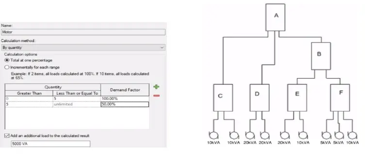
What is the demand load on Panel B?

Correct Answer: B. 55kVA
Explanation:

In Revit Electrical, Demand Factors are applied through Load Classifications to compute an Estimated Demand Load rather than simply summing connected loads. The documentation states: ''You use demand factors to adjust the rating of the main service... Demand factors are assigned to load classifications, and load classifications are assigned to device connectors. The estimated load for a device is calculated by multiplying the load by the demand factor. ... The panel schedule can also display the load for each load classification.''

In the exhibit's Demand Factor definition (for the Motor classification), the Calculation method is By quantity with Total at one percentage selected. Two quantity ranges are defined: 0--5 items at 100% and 5--unlimited at 50%. An additional checkbox adds an extra fixed load of 5000 VA to the calculated result. (This follows Revit's behavior of applying the selected demand factor to the connected load and then adding any specified additional load to the result for that classification.)

Panel B feeds only panels E and F. The connected motor loads downstream are:

Panel E: 20 kVA + 10 kVA = 30 kVA

Panel F: 5 kVA + 5 kVA + 10 kVA = 20 kVA

Total connected motor load on B = 30 + 20 = 50 kVA (five items).

Because five items fall in the 0--5 range at 100%, the demand factor is 100% 50 kVA. Per the definition, add an additional load of 5000 VA (5 kVA) to the calculated result:

Demand Load on Panel B = 50 kVA 100% + 5 kVA = 55 kVA.

Therefore, the correct choice is 55 kVA.

References: Revit MEP Electrical documentation -- Demand Factors (assignment to load classifications, multiplication to compute estimated load, and display in panel schedules).


Question 9

Refer to exhibit.

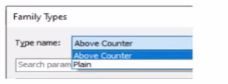
A family in a project contains the following types:

The following edits are made in the Family Editor and loaded into the project:

1. The type Plain is renamed to Standard

2 A new type is added named GFCI

Which types does this family now have in the project?

1. The type Plain is renamed to Standard

Correct Answer: B. Above Counter. GFCI. Standard
Explanation:

In Revit, when editing a family in the Family Editor and reloading it into a project, Revit handles type changes using specific update rules. Types that are renamed overwrite their earlier version in the project because they retain the same internal type ID. Types that are added to the family also appear in the project once reloaded.

Initially, the family contains two types:

Above Counter

Plain

The changes made in the Family Editor are: 1 Rename Plain Standard 2 Add a new type named GFCI

According to documented Revit behavior for type updates:

''When a family is reloaded into the project, any renamed family type replaces its previous version while maintaining its parameter assignments. Newly created types are added as additional family types available for placement within the project.''

Therefore:

Plain no longer exists because it was renamed

Standard now exists in its place

GFCI is added as a new family type

Above Counter remains unchanged

Thus, the family in the project now contains: Above Counter GFCI Standard

This matches answer choice: B. Above Counter, GFCI, Standard


Question 10

An electrical designer has noticed lighting fixtures present in an architectural linked model. Which tool should be used to place an instance of those fixtures in the current electrical model while maintaining the position from the architectural model?

Correct Answer: A. Copy/Monitor
Explanation:

When lighting fixtures placed in an architectural linked model need to be replicated in the electrical model while maintaining their exact positions, the correct tool is Copy/Monitor.

This Revit feature allows the electrical designer to copy elements---like lighting fixtures---from a linked model into their project, while establishing a monitoring relationship between the original (architectural) and copied (electrical) instances.

From the Autodesk Revit MEP User's Guide -- Chapter 55 ''Multi-Discipline Coordination'' (pages 1349--1357):

''Use the Copy/Monitor tool to copy MEP fixtures from an architectural model into an MEP project, and monitor them for changes.'' (Revit MEP User's Guide, p. 1350)

''To copy fixtures from a linked model:

Click Collaborate tab Coordinate panel Copy/Monitor Select Link.

Select the linked architectural model in the drawing area.

Click Copy and select the lighting fixtures to copy.

Click Finish. Revit MEP copies the fixtures to the current project and establishes monitoring relationships.''* (Revit MEP User's Guide, p. 1356)

Behavior and Benefits:

The copied lighting fixtures maintain the same location, orientation, and type mapping as in the linked model.

Any changes (move, delete, or modify) made by the architect in the linked model will trigger a coordination review in the electrical model.

This ensures accurate positioning and easy coordination between disciplines.

''When you select a copied fixture in the current project, the monitor icon displays next to the fixture, indicating that it has a relationship with the original fixture in the linked model.'' (Revit MEP User's Guide, p. 1357)

''If copied fixtures are moved, changed, or deleted in the linked model, Revit MEP notifies the engineers of the changes during Coordination Review.'' (Revit MEP User's Guide, p. 1357)