Limited-Time Offer: Enjoy 50% Savings! Ends in 00h 00m 00s Coupon code: 50OFF
Skip to content

Free HP HPE Campus Access Switching Expert Written Exam HPE7-A06 Exam Questions

Page: 1 / 7 Total 70 questions

Want more questions? Get Premium Access.

Question 1

A senior engineer from the network operations team has reported an intermittent problem where some PoE-powered devices are randomly losing power. During your investigation, you found that port 1 of the Acc-1 switch is currently presenting the behavior shown in the CLI output for the Acc-1.
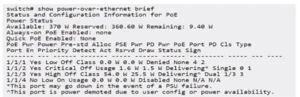
What is a probable causa lot poor 1/1/1 is denying PoE?

Correct Answer: B. switch PoE power budget exceeded
Explanation:

The question involves intermittent PoE-powered device power loss on port 1/1/1 of an AOS-CX switch (Acc-1), with CLI output (not provided) indicating a PoE issue. The task is to identify a probable cause.

Analysis of Options:

Option A: Incorrect. AOS-CX switches typically support PoE Class 4 (802.3at, 30W), sufficient for most devices.

Option B: Correct. If the switch's PoE power budget is exceeded, it may deny power to port 1/1/1, causing intermittent device failures.

Option C: Incorrect. Low PoE port priority may deprioritize the port but is less likely to cause complete power loss compared to budget issues.

Option D: Incorrect. Manual disabling of PoE would cause consistent power loss, not intermittent issues.

Why Option B is Correct: AOS-CX switches have a finite PoE power budget (e.g., 370W or 740W, depending on the model and power supply). If the total power demand from connected devices exceeds this budget, the switch denies power to some ports, often intermittently as devices cycle or negotiate power. For port 1/1/1, this could manifest as random power loss for the connected device. The CLI output likely shows a ''power denied'' status (e.g., via show power-over-ethernet brief). Checking the PoE budget (show power-over-ethernet) and upgrading power supplies or prioritizing critical ports resolves the issue, aligning with HPE Aruba Networking's PoE troubleshooting guidelines.

Relevance to Certification Objectives:

Connectivity (9%): Troubleshooting PoE deployment issues.

Troubleshooting (10%): Diagnosing power-related issues in campus networks.

Switching (19%): Implementing PoE configurations for Layer 2 devices.


HPE Aruba Networking AOS-CX Configuration Guide: PoE Configuration and Troubleshooting.

HPE7-A06 Study Guide: Covers PoE management and diagnostics.

HPE Aruba Networking Technical Documentation: PoE Budget Troubleshooting.
Question 2

An OSPF router has teamed a path to an external network oy both an El and an E2 advertisement, both routes having the same path cost. Which path -will the router prefer?

Correct Answer: D. The router will prefer the E1 path.
Explanation:

The question involves an OSPF router receiving both an E1 (External Type 1) and an E2 (External Type 2) advertisement for an external network with the same path cost. The task is to determine which path the router will prefer.

Analysis of Options:

Option A (ECMP): Equal-Cost Multi-Path (ECMP) is used when multiple paths have the same total cost, but E1 and E2 routes have different metric calculations, so ECMP does not apply here.

Option B (Prefer E2): Incorrect, as E2 routes are preferred only when E1 routes are not present or have a higher total cost.

Option C (Suppressed): OSPF does not suppress routes due to path conflicts; it selects the best path based on metrics.

Option D (Prefer E1): Correct. OSPF prefers E1 routes over E2 routes because E1 routes include the internal cost to the ASBR (Autonomous System Boundary Router) plus the external cost, providing a more accurate total cost.

Why Option D is Correct: In OSPF, external routes are advertised as E1 or E2. E1 routes include both the external cost (advertised by the ASBR) and the internal cost to reach the ASBR, making them more precise for path selection. E2 routes only consider the external cost and are the default for redistributed routes unless explicitly configured as E1. When an OSPF router receives both E1 and E2 routes with the same external cost, it prefers the E1 route because it accounts for the total path cost, including internal network topology. This is per OSPF standards (RFC 2328).

Relevance to Certification Objectives:

Routing (16%): Involves designing and troubleshooting OSPF routing topologies, including external route types (E1 vs. E2).

Troubleshooting (10%): Includes analyzing OSPF path selection to resolve routing issues.


HPE Aruba Networking AOS-CX Configuration Guide: OSPF Configuration, detailing E1 and E2 route types.

HPE7-A06 Study Guide: Covers OSPF external route selection and path preference.

RFC 2328: OSPF Version 2, explaining E1 and E2 route metrics and preference.

Question 3

Ever since a recent firewall change at your WAN/lnternet edge, the 8GP state in your VSX pair has not returned to Established. What should you check to restore BGP functionality at the site?

Correct Answer: B. Confirm that appropriate TCP ports are still allowed.
Explanation:

The BGP state on a VSX pair is stuck (not 'Established') after a recent firewall change at the WAN/Internet edge, where the BGP peering likely occurs.

BGP and Firewalls: BGP establishes sessions using TCP port 179. Firewalls located between BGP peers must explicitly permit TCP port 179 traffic bidirectionally for the peering to establish and maintain. Firewall changes are a frequent cause of broken BGP sessions.

Troubleshooting Steps After Firewall Change: The most logical first step is to verify that the firewall change did not inadvertently block TCP port 179 between the configured BGP neighbor IP addresses.

Analysis of Options:

A: Restarting routing service is disruptive and not the first step.

B: Confirming that appropriate TCP ports (specifically 179) are still allowed through the firewall directly addresses the most probable cause related to the firewall change event.

C: Restarting NAT service is likely irrelevant unless NAT is incorrectly configured for BGP peers.

D: Confirming the peer AS is a basic configuration check but less likely related to the firewall change event than port blocking.

Conclusion: Given the problem occurred immediately following a firewall change, verifying that the firewall still permits TCP port 179 between the BGP peers is the most direct and likely troubleshooting step.


Question 4

You are configuring an HPE Aruba Networking Gateway Ouster with AOS-10. What is true about 802.1 X functionality in combination with gateways? (Select two.)

Correct Answer: B. The UDG remains fixed on L2-connected gateways but not on 1.3-connected gateways.; D. The gateways are used as a RADIUS proxy, while the AP is the authenticator.
Explanation:

This question asks about 802.1X functionality in an AOS-10 environment involving Gateway Clusters.

AOS-10 Gateway/802.1X Architecture:

Authenticator: The Access Point (AP) typically acts as the 802.1X authenticator, handling EAPoL frames with the client.

RADIUS Proxy: The Gateway Cluster (specifically the cluster leader or UDG anchor) often acts as a RADIUS proxy, forwarding RADIUS messages between the APs and the central RADIUS server (e.g., ClearPass). This simplifies RADIUS configuration as the server only needs to know about the gateway cluster.

CoA: Change of Authorization messages from the RADIUS server are typically sent to the device acting as the RADIUS client, which is the Gateway Cluster when operating in proxy mode.

Mobility (L2 vs L3): Roaming behavior and User Designated Gateway (UDG) assignment can differ based on whether clients maintain their IP address (L2 mobility) or potentially require new IP information (L3 mobility). L2-connected gateway deployments generally allow for more seamless UDG persistence compared to L3-connected deployments where the client might roam across subnet boundaries managed by different gateways.

Re-authentication: Seamless roaming mechanisms aim to minimize full re-authentications during roaming events.

Analysis of Options:

A: Full re-authentication after re-association on L3-connected gateways might occur in some scenarios but contradicts the goal of seamless roaming.

B: States the UDG remains fixed on L2-connected but not on L3-connected gateways. This aligns with the architectural differences in handling mobility across L2 vs L3 boundaries within a cluster.

C: Incorrect. CoA is generally sent to the RADIUS client/proxy (the Gateway Cluster), not always directly to the APs.

D: Correct. Gateways commonly act as a RADIUS proxy, while the AP remains the authenticator handling EAPoL with the client.

E: Incorrect. The RADIUS proxy function is not limited to only Tunnel and Bridged modes.

Conclusion: Options B and D accurately describe common characteristics of 802.1X operation within an AOS-10 Gateway Cluster architecture.


Question 5

An HPE Aruba Networking CX switch administrator wants to monitor all inter-switch connections and change their descriptions dynamically with Python script and NAE engine. The administrator has written the script template and uploaded it to the switch GUI. After the upload, not all data is stored as planned.

Which things should be checked first? (Select three.]

Correct Answer: B, C, E, E
Explanation:

An NAE (Network Analytics Engine) Python script designed to monitor links and update descriptions isn't storing data as planned. We need the first things to check (select three).

NAE Components & Troubleshooting: NAE involves Agents running Scripts, often triggered by Monitors observing system state (like interface status or LLDP changes). Failures can occur in any component or due to resource issues.

Initial Checks:

Script (script usage - C): Check the script itself for syntax errors, logic flaws, status, and logs (show nae script <name> [status|log]). Ensure it's uploaded correctly and enabled.

Agent (Agent usage - B): Check the agent configured to run the script. Is it running? Are its parameters correct? Are there errors associated with the agent? (show nae agent [status|detail]). Check agent resource limits.

Monitor (monitor usage - E): If the script relies on a monitor to trigger or gather data, check the monitor's status, configuration, and associated conditions (show nae monitor [status|detail]). Is the monitor detecting the intended events?

Resources (Processor/Memory/Flash - D, F, A): General switch health is important. High CPU (D) or memory (F) usage could prevent the script/agent from running correctly. If the script is supposed to store data persistently (e.g., write to a file or NAE database), check flash memory usage (A) or NAE database limits.

Conclusion: When troubleshooting NAE, the core components to check first are the Script itself (C), the Agent running it (B), and any Monitors it depends on (E). These cover the specific NAE elements involved. General system resources (D, F, A) are secondary checks if the core components appear configured correctly but still fail.


Question 6

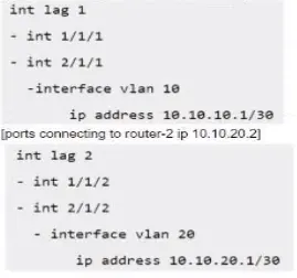
A customer has configured eBGP peering using local AS 65000 with two routers from a CX 6300 VSF stack with the following switch ports:

[ports connecting to router-1 10.10.10.2]

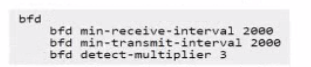
The LAGs are connected lo third-party L2 switches, which are used as a transit network for the remote eBGP routers. To optimise the possible BGP peering issues. The AOS-CX switch Is configured with the global settings:

What needs to be done on the AOS_CX switch to enable the bidirectional forwarding with the eBGP peers?

Correct Answer: B. Option B
Explanation:

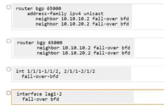
The goal is to enable Bidirectional Forwarding Detection (BFD) for eBGP neighbors 10.10.10.2 and 10.10.20.2 on the AOS-CX VSF stack (AS 65000). Global BFD settings are already configured. We need the specific commands to link BFD state to the BGP neighbor relationship.

BFD for BGP Configuration: Requires enabling the fall-over bfd parameter for the specific neighbor within the router bgp configuration hierarchy.

Analyzing the Options (New Image):

Option 1 (Top):

router bgp 65000

address-family ipv4 unicast

neighbor 10.10.10.2 fall-over bfd

neighbor 10.10.20.2 fall-over bfd

This enables BFD specifically within the ipv4 unicast address family context for both neighbors. This is a valid configuration location.

Option 2 (Second):

router bgp 65000

neighbor 10.10.10.2 fall-over bfd

neighbor 10.10.20.2 fall-over bfd

This enables BFD directly under the main neighbor configuration lines within router bgp 65000. This typically applies BFD to all address families configured for that neighbor relationship (including IPv4 unicast). This is also a valid and common configuration location.

Option 3 (Third):

int 1/1/1-1/1/2, 2/1/1-2/1/2

fall-over-bfd

Incorrect. Applies BFD configuration under an interface range context, which is not how BFD is linked to BGP sessions.

Option 4 (Bottom):

interface lag1-2

fall-over bfd

Incorrect. Applies BFD configuration under an interface LAG range context, which is not how BFD is linked to BGP sessions.

Comparing Valid Options (1 vs 2): Both Option 1 and Option 2 correctly use the fall-over bfd command under router bgp. Option 1 provides per-address-family granularity, while Option 2 applies it to the neighbor generally. Without a specific requirement to enable BFD only for IPv4, applying it at the neighbor level (Option 2) is often simpler and sufficient. Both achieve the goal for the required IPv4 peering. In many documentation examples, the configuration is shown at the neighbor level unless per-AF control is explicitly needed.

Conclusion: Both Option 1 and Option 2 show valid configuration methods. Option 2 is arguably slightly more common/general when BFD is desired for the overall neighbor relationship.


Question 7

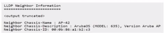
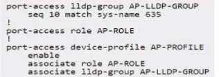
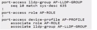
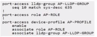
Which set of commands will apply the device profile 'AP' to the device shown in the LLDP neighbor output below?

A)

B)

C)

D)

Correct Answer: A. Option A
Explanation:

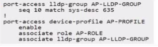
The goal is to configure the switch to automatically apply a specific device profile (named AP-PROFILE in the options) to ports where an Aruba AP Model 635 connects, using LLDP information for detection.

LLDP Information: The LLDP neighbor output shows:

Neighbor Chassis-Description: ArubaOS (MODEL: 635), Version Aruba AP

Neighbor Chassis-Name: AP-42

Device Profile Mechanism: This involves creating an LLDP group that matches specific attributes of the desired device, creating a device profile containing the desired port configurations (VLAN, PoE, QoS, Role, etc.), associating the profile with the LLDP group, and enabling the feature globally.

Analyzing Configuration Options: All options configure an LLDP group AP-LLDP-GROUP and a device profile AP-PROFILE. The key is the matching condition within the LLDP group and the completeness of the profile configuration.

Matching Condition:

Options A, C, D use seq 10 match sys-desc 635. This condition checks if the LLDP System Description contains the string '635'. Based on the output (...MODEL: 635...), this condition will match the target AP.

Option B uses seq 10 match sys-name 635. This checks if the LLDP System Name contains '635'. The output shows Neighbor Chassis-Name: AP-42. This condition will not match.


Question 8

The customer is experiencing periodic uplink congestion between campus-1's AGG-1 and core. This has boon negatively affecting voice communications. The VOIP phones edge mark their packets with DSCP EF. The uplink from AGG-1 to core is LAG1.

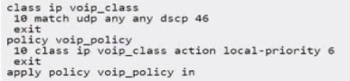
The customer has already configured the following class and policy on AGG-1:

Based on this policy, which scrip), when deployed on AGG-1. will improve the reliable forwarding of voice traffic between AGG-1 and its uplink to the core?

A)

B)

C)

D)

Correct Answer: B. Option B
Explanation:

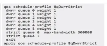
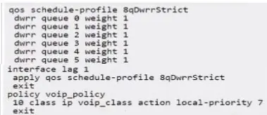
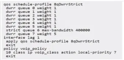
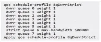
The problem describes uplink congestion affecting VoIP traffic (marked with DSCP EF, value 46) on AGG-1's LAG1 uplink. The existing configuration classifies this traffic into voip_class and applies voip_policy inbound, setting local-priority 6. To improve reliable forwarding during congestion, VoIP traffic needs strict priority queuing on the egress interface (LAG1).

Analysis of Options:

Option A applies a QoS schedule profile globally but doesn't modify the policy's local-priority or apply the schedule profile specifically to the congested LAG.

Option B modifies voip_policy to set local-priority 7 (mapping DSCP 46 traffic to queue 7) and applies the 8qDwrStrict schedule profile to the egress interface lag 1. In the 8qDwrStrict profile, queue 7 is configured for strict priority, ensuring voice traffic gets precedence over lower-priority traffic during congestion. This aligns with best practices for QoS for VoIP.

Option C also sets local-priority 7 and applies the schedule profile to lag 1, but the profile itself configures queue 7 with DWRR (Deficit Weighted Round Robin) instead of strict priority, which is less suitable for delay-sensitive voice traffic.

Option D applies a schedule profile globally and uses DWRR for queue 7.

Conclusion: Option B is the correct solution because it maps the DSCP EF traffic to the highest local priority (7) and applies a QoS schedule profile to the specific congested uplink (lag 1) that treats queue 7 with strict priority. This ensures voice traffic is prioritized reliably.


Question 9

You want to use OSPF to advertise a only .\16 summary route for the SVls below to a neighbor In the same area (area 0).

Which configuration will achieve this?

A)

B)

C)

D)

E.

Correct Answer: E. Option E
Explanation:

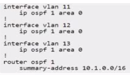
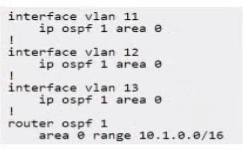
The goal is to configure OSPF on a router so that it advertises only a 10.1.0.0/16 summary route for the specific SVIs (VLAN 11, 12, 13, assumed to be within the 10.1.x.x range) to its OSPF neighbors within the same area (Area 0).

OSPF Intra-Area Behavior: A fundamental principle of OSPF (link-state protocols) is that all routers within the same area must have an identical Link State Database (LSDB) for that area. This means all routers learn about all the specific networks (Type-1 Router LSAs, Type-2 Network LSAs) within their area. OSPFv2 does not support summarizing routes in a way that hides specific network LSAs from other routers within the same area. Summarization occurs only at area boundaries (by ABRs using Type-3 Summary LSAs via the area range command) or for external routes redistributed into OSPF (by ASBRs using Type-5 External LSAs via the summary-address command).

Analysis of Options:

A) area 0 range 10.1.0.0/16: This command is used on an Area Border Router (ABR) to summarize routes originating from Area 0 when advertising them into another area (e.g., the backbone). It does not affect LSA flooding within Area 0. It also includes redistribute connected, which is unrelated here.

B) summary-address 10.1.0.0/16: This command is used on an Autonomous System Boundary Router (ASBR) to summarize external routes being redistributed into OSPF. It is not used for summarizing internal OSPF routes like SVIs defined within an OSPF area.

C) & D) summary-address 10.1.0.0/16: Same issue as B; incorrect command for summarizing internal OSPF routes.

E) area 0 range 10.1.0.0/16: Similar to A, this uses the area range command. It correctly shows the SVIs configured for OSPF Area 0 first. However, like A, this command performs inter-area summarization on an ABR and does not suppress the specific LSAs within Area 0.

Conclusion: The question asks for something that OSPFv2 cannot do: advertise only a summary route within the same area while suppressing specifics. Therefore, none of the configurations will achieve the exact stated outcome. However, if the question is flawed and intends to ask which configuration uses the correct command structure for summarizing internal OSPF routes (even if only effective between areas), then the area range command is the relevant one. Both A and E use this command. Option E is slightly better structured as it shows the interfaces being added to OSPF Area 0 first. Assuming this is the intended direction despite the impossibility of the specific request, E is the most plausible choice among the given options.


Question 10

Refer to the exhibit which illustrates the current configuration of Router-1.

Clients of VLAN 10 require access to services hosted in the 10.1.100.0/24 subnet. This 'equites one 01 more routes to be added to Rculer-1 that do not currently exist.

Which script would install a route from 10.2.10.0/24 to 10.1.100.0/24 on Router-1? A return path is not required as part of this answer.

Correct Answer: D. ip route 0.0.0.0/0 10.255.101.11 vrf service ip route 10.255.101.0/24 1/1/1 vrf IoT-Medical ip route 10.1.100.0/24 10.255.101.11 vrf IoT-Medical
Explanation:

The goal is to add a static route on Router-1 to allow clients in VLAN 10 (subnet 10.2.10.0/24, presumably in VRF 'IoT-Medical' based on options) to reach services in the 10.1.100.0/24 subnet. The exhibit indicates interface 1/1/1 (IP 10.255.101.10/24) is in VRF 'service', and the likely next hop towards the destination is Core-1 at 10.255.101.11 (also implied to be reachable via VRF 'service'). This requires adding a route in the source VRF ('IoT-Medical') pointing towards the destination via the next hop in the 'service' VRF.

Static Route Syntax (with VRF): ip route <destination_prefix> <next-hop-ip> [vrf <source-vrf>]

Analysis of Options:

A: Claims Core-1 isn't in VRF 'service', contradicting the likely setup.

B: Uses unusual interface:ip syntax (1/1/1:10.255.101.11). Defines the route in VRF 'IoT-Medical'.

C: Uses interface 1/1/1 as the next hop. This is less specific than using the IP address and relies on the interface being point-to-point or having proxy ARP enabled. Defines the route in VRF 'IoT-Medical'.

D: ip route 10.1.100.0/24 10.255.101.11 vrf IoT-Medical. This uses the standard syntax to define a static route for the destination 10.1.100.0/24 via the next-hop IP 10.255.101.11 within the context of the IoT-Medical VRF. The successful function of this route depends on inter-VRF routing (route leaking) being configured between 'IoT-Medical' and 'service' VRFs, but the command itself correctly defines the desired static route.

Conclusion: Option D provides the correct and standard command syntax to configure the required static route within the specified source VRF ('IoT-Medical').