
Limited-Time Offer: Enjoy 50% Savings! Ends in 00h 00m 00s Coupon code: 50OFF
Skip to content

Free Juniper Data Center, Specialist JN0-481 Exam Questions

Page: 1 / 7 Total 65 questions

Want more questions? Get Premium Access.

Question 1

You have a configuration deviation in the Juniper Apstra dashboard. What does this anomaly indicate in this scenario?

Correct Answer: C. A device's configuration has been changed using a method outside of Apstra.
Explanation:

A configuration deviation (also called a configuration anomaly) in Apstra indicates that the device's running configuration differs from Apstra's intended (golden) configuration for that node. In day-to-day operations, this most commonly occurs when an operator makes a change outside of Apstra's control, such as entering commands directly on the device CLI (for example, on a Junos v24.4 switch), using another automation system, or applying an out-of-band configuration method.

Apstra continuously compares the device's operational configuration against what it expects based on blueprint intent. When it detects drift, it raises a deviation anomaly so operators can decide how to restore compliance. Typical remediations are either (1) remove/revert the out-of-band change so the device matches intent again, or (2) explicitly acknowledge the change in Apstra (for example, via an accept/suppress workflow, depending on the exact UI action and version), so the deviation is no longer treated as unexpected.

While it is also possible for a deviation to be triggered by a device not accepting a rendered command (capability mismatch), the question asks what the anomaly indicates in this scenario; the primary meaning of ''configuration deviation'' is configuration changed outside of Apstra and therefore the network is no longer aligned with the intended state. That corresponds to option C.

Question 2

What are two types of virtual networks defined inside Juniper Apstra software? (Choose two.)

Correct Answer: A. VLAN; C. VXLAN
Explanation:

In Apstra 5.1, a Virtual Network (VN) is Apstra's abstraction for a Layer 2 forwarding domain that groups endpoints into a logical segment across the fabric. Apstra defines virtual networks as being constructed using either VLANs or VXLANs. A VLAN-based VN represents a Layer 2 domain identified by a VLAN ID and is typically used where you want traditional VLAN semantics (often in smaller environments, migration scenarios, or designs where an overlay is not required). A VXLAN-based VN represents the same Layer 2 intent but uses a VXLAN VNI for scalable overlay segmentation, which is the common approach in EVPN-VXLAN data center fabrics.

In an IP fabric architecture, VXLAN provides encapsulation to carry tenant segments over the routed underlay, while EVPN provides the control-plane signaling for MAC/IP reachability. Junos v24.4 leaf devices act as VTEPs, mapping local VLANs/bridge-domains to VNIs and participating in EVPN for advertisement and convergence. Apstra's VN construct allows you to create the segment once (as VLAN or VXLAN type), then consistently attach it to racks, ports, and endpoints through intent-driven workflows (such as connectivity templates and virtual network assignments).

''L2 VPN'' and ''L3 VPN'' are service provider terms and are not the VN ''types'' in Apstra's data center reference design. In Apstra, tenant L3 separation is modeled by routing zones (VRFs), while the VN itself is specifically either VLAN-based or VXLAN-based.

Verified Juniper sources (URLs):

https://www.juniper.net/documentation/us/en/software/apstra5.1/apstra-user-guide/topics/concept/virtual-networks.html

https://www.juniper.net/documentation/us/en/software/apstra5.1/apstra-user-guide/topics/topic-map/virtual-network-create.html


Question 3

You have a virtual network that needs controlled access to other virtual networks in the same routing zone. Using the Juniper Apstra Ul. which feature would be used to accomplish this task?

Correct Answer: D. security policy
Explanation:

A security policy is the feature that would be used to accomplish the task of controlling access to other virtual networks in the same routing zone using the Juniper Apstra UI. A security policy allows you to define rules that specify which traffic is allowed or denied between different virtual networks, IP endpoints, or routing zones. A security policy can be applied to one or more virtual networks in the same routing zone, and it can use various criteria to match the traffic, such as source and destination IP addresses, protocols, ports, or tags. A security policy can also support DHCP relay, which enables the forwarding of DHCP requests from one virtual network to another. The other options are incorrect because:

A . interface policy is wrong because an interface policy is a feature that allows you to configure the interface parameters for the devices in a blueprint, such as interface names, speeds, types, or descriptions. An interface policy does not affect the access control between different virtual networks in the same routing zone.

B . anti-affinity policy is wrong because an anti-affinity policy is a feature that allows you to prevent certain devices or logical devices from being placed in the same rack or leaf pair in a blueprint. An anti-affinity policy is used to enhance the availability and redundancy of the network, not to control the access between different virtual networks in the same routing zone.

C . routing policy is wrong because a routing policy is a feature that allows you to configure the routing parameters for the devices in a blueprint, such as routing protocols, autonomous system numbers, route filters, or route maps. A routing policy does not affect the access control between different virtual networks in the same routing zone, unless the routing policy is used to filter or modify the routes exchanged between different routing zones.Reference:

Security Policy

Interface Policy

Anti-Affinity Policy

Routing Policy


Question 4

You are creating a template using Juniper Apstr

a. In this scenario, what is a rack-based design compared to a pod-based design?

Correct Answer: B. A rack-based design refers to a three-stage Clos, and a pod design refers to a five-stage Clos.
Explanation:

In Apstra 5.1, templates are used to describe the intended structure of a data center fabric. A rack-based template is used to build the common 3-stage Clos model (spines connected to racks containing leaf/top-of-rack switches and endpoints). In this design, you define the spine logical devices, select one or more rack types, specify rack counts, and define the intended connectivity between spines and racks. This directly models a leaf-spine IP fabric typically used for EVPN-VXLAN in modern data centers.

A pod-based template, by contrast, is explicitly used to build 5-stage Clos networks. In Apstra's terminology, a pod-based template is essentially a ''template of templates'': it combines one or more rack-based templates (each representing a 3-stage pod) and adds an additional superspine layer to interconnect those pods into a larger, scalable fabric. This is the architectural distinction: rack-based describes the leaf-spine pod, while pod-based describes the multi-pod superspine architecture.

For Junos v24.4 EVPN-VXLAN deployments, the difference matters operationally because 5-stage fabrics introduce additional tiers and scaling considerations (for example, superspine connectivity and expanded ECMP domains). Apstra's template hierarchy ensures consistent intent modeling across both 3-stage and 5-stage topologies without requiring operators to manually redesign the fabric logic each time they scale out.

Verified Juniper sources (URLs):

https://www.juniper.net/documentation/us/en/software/apstra5.1/apstra-user-guide/topics/concept/templates.html

https://www.juniper.net/documentation/us/en/software/apstra5.1/apstra-user-guide/topics/task/template-create-pod-based.html

https://www.juniper.net/documentation/us/en/software/apstra5.1/apstra-user-guide/topics/topic-map/5-stage-clos.html


Question 5

What are two agent processes that operate within the Juniper Apstra device agent? (Choose two.)

Correct Answer: C. Telemetry agent; D. Deployment agent
Explanation:

In Apstra deployments that use on-box device agents, the agent package installs multiple processes inside the switch's NOS namespace to provide an isolated runtime environment for Apstra control and telemetry collection. Two of those processes are the Telemetry Agent and the Deployment Agent. The Telemetry Agent is responsible for collecting operational information from the device---such as LLDP neighbor details, routing-related state, and interface information---and sending that telemetry upstream to Apstra. This telemetry is a key input for closed-loop assurance in EVPN-VXLAN fabrics, where Apstra correlates underlay health (interfaces, neighbors, sessions) with overlay services.

The Deployment Agent is responsible for receiving configuration content pushed from Apstra and applying it on the device. In a Junos v24.4 fabric, this is the component that enables Apstra to converge device configuration to the blueprint's intent (for example, BGP underlay, EVPN signaling, and VXLAN constructs) without requiring manual CLI workflows. Both agents are typically idle most of the time, becoming active when Apstra needs to apply configuration changes or when significant state changes trigger telemetry updates.

Other listed options---''routing agent'' and ''authentication agent''---are not the named Apstra device-agent processes described for the on-box agent package in Juniper documentation.

Verified Juniper sources (URLs):

https://www.juniper.net/documentation/us/en/software/apstra4.2/apstra-server-and-security-guide/topics/concept/apstra-device-agents.html


Question 6

What does VXLAN use to uniquely label and identify broadcast domains?

Correct Answer: C. Virtual Network Identifier (VNI)
Explanation:

In a VXLAN overlay, each Layer 2 broadcast domain (the logical equivalent of a VLAN/bridge domain) is identified by a 24-bit VXLAN Network Identifier (VNI) carried in the VXLAN header. This VNI is what allows the overlay to scale far beyond traditional VLAN space (12-bit VLAN IDs), enabling up to ~16 million distinct segments. In an EVPN-VXLAN data center fabric, Junos v24.4 leaf switches operate as VTEPs and map local bridge domains (often associated with VLANs on server-facing ports) to a VNI. When traffic is sent across the routed underlay, the leaf encapsulates Ethernet frames into VXLAN packets and inserts the VNI so the receiving VTEP can place the frame into the correct broadcast domain on decapsulation.

Apstra 5.1 abstracts this mapping through virtual networks and resource allocation: when you define a VXLAN-based virtual network, Apstra allocates a VNI from the appropriate pool and consistently programs the necessary constructs on all participating leaves. The key point is that VNI is the unique identifier in the VXLAN data plane used to label the broadcast domain across the IP fabric; VLAN IDs may exist locally at the edge for tagging, but the globally significant overlay identifier is the VNI.

Verified Juniper sources (URLs):

https://www.juniper.net/documentation/us/en/software/junos/evpn/topics/topic-map/sdn-vxlan.html


Question 7

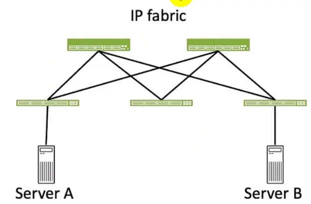
Exhibit.

Referring to the exhibit, how many broadcast domains will an Ethernet frame pass through when traversing the IP fabric from Server A to Server B?

Correct Answer: C. 2
Explanation:

Referring to the exhibit, the image shows a simplified diagram of an IP fabric network connecting two servers, labeled as Server A and Server B. The IP fabric is a network architecture that uses a Clos topology to provide high bandwidth, low latency, and scalability for data center networks.The IP fabric consists of spine and leaf devices that use BGP as the routing protocol and VXLAN as the overlay technology1.

A broadcast domain is a logical portion of a network where any device can directly transmit broadcast frames to other devices at the data link layer (OSI Layer 2). A broadcast frame is a frame that has a destination MAC address of all ones (FF:FF:FF:FF:FF:FF), which means that it is intended for all devices in the same broadcast domain.A broadcast domain is usually bounded by a router, which does not forward broadcast frames to other networks2.

In the exhibit, there are two broadcast domains that an Ethernet frame will pass through when traversing the IP fabric from Server A to Server B. The first broadcast domain is the one that contains Server A and the leaf device that it is connected to. The second broadcast domain is the one that contains Server B and the leaf device that it is connected to. The IP fabric itself is not a broadcast domain, because it uses IP routing and VXLAN encapsulation to transport the Ethernet frames over the Layer 3 network. Therefore, the statement C is correct in this scenario.

The following three statements are incorrect in this scenario:

A . 1. This is not true, because there are not one, but two broadcast domains that an Ethernet frame will pass through when traversing the IP fabric from Server A to Server B. The IP fabric itself is not a broadcast domain, because it uses IP routing and VXLAN encapsulation to transport the Ethernet frames over the Layer 3 network.

B . 4. This is not true, because there are not four, but two broadcast domains that an Ethernet frame will pass through when traversing the IP fabric from Server A to Server B. The spine devices and the leaf devices that are not connected to the servers are not part of the broadcast domains, because they use IP routing and VXLAN encapsulation to transport the Ethernet frames over the Layer 3 network.

D . 3. This is not true, because there are not three, but two broadcast domains that an Ethernet frame will pass through when traversing the IP fabric from Server A to Server B. The IP fabric itself is not a broadcast domain, because it uses IP routing and VXLAN encapsulation to transport the Ethernet frames over the Layer 3 network.


IP Fabric Overview

Broadcast Domain - NetworkLessons.com

Question 8

You have accessed your deployed blueprint and see the banner shown in the exhibit.

Which two statements are correct in this scenario? (Choose two.)

Correct Answer: B. There are changes that are not active on the fabric.; D. There are anomalies that must be addressed.
Explanation:

In Apstra 5.1, the top-level blueprint banner uses tab indicators (colored badges) to summarize blueprint status across areas such as Staged, Uncommitted, Active, and Analytics. The presence of an Uncommitted indicator signifies that there are staged modifications that have not yet been committed and therefore are not part of the active, deployed intent. That directly corresponds to the statement that changes exist which are not active on the fabric.

At the same time, the banner shows an Active indicator in an alarm state, which reflects that the running fabric has issues requiring attention---commonly surfaced as anomalies (for example, configuration deviation, interface/link faults, protocol/session issues, or service-impacting conditions). In Apstra's operational model, these issues appear as anomalies that operators should investigate and remediate to restore compliance and health. Therefore, the statement that there are anomalies that must be addressed is also correct.

The remaining options are not implied by this banner alone. Device profile assignment and resource assignment are build-time tasks, but their absence is not what the Uncommitted/Active alert indicators are specifically communicating here. The banner is highlighting uncommitted intent changes and active anomalies that affect the deployed blueprint state and assurance posture.

Verified Juniper sources (URLs):

https://www.juniper.net/documentation/us/en/software/apstra5.1/apstra-user-guide/topics/concept/uncommitted.html

https://www.juniper.net/documentation/us/en/software/apstra5.0/apstra-user-guide/topics/topic-map/anomalies-service-active.html

https://cloudlabs.apstra.com/labguide/Cloudlabs/6.0.0/test-drive-guide/lab1-junos-5_blueprints_.html


Question 9

What are two available Juniper Apstra template types? (Choose two.)

Correct Answer: A. Collapsed; B. Rack-based
Explanation:

In Juniper Apstra 5.1, a template is a design abstraction used to create a blueprint. It captures the intended topology shape and design rules without tying the design to a specific vendor's CLI. Apstra supports multiple template types to match common data center fabric architectures.

A rack-based template is used for the standard three-stage Clos (leaf--spine) approach. In this model, you define the spine logical devices and one or more rack types (containing leaf devices and optional endpoint constructs). This is the dominant pattern for EVPN-VXLAN IP fabrics: leaf switches provide server attachment, VXLAN encapsulation (VTEP function), and optional IRB gateways, while spines provide high-capacity L3 transit with ECMP.

A collapsed template is used for a spine-less (spineless) topology. Instead of a separate spine tier, a collapsed design models a fabric where leaf nodes interconnect in a mesh-like arrangement (as supported by the template type) to provide underlay reachability and redundancy. This can be useful for smaller environments or edge data centers where a full spine tier is unnecessary.

''Compressed'' and ''device-based'' are not Apstra template types. Junos v24.4 is relevant when the blueprint is instantiated and deployed, but the template type selection is an Apstra design-time decision that determines the fabric topology class.


Question 10

Which Root Cause Identifier is currently supported in Juniper Apstra software?

Correct Answer: B. Connectivity
Explanation:

In Juniper Apstra 5.1, Root Cause Identification (RCI) is implemented with a currently supported model focused on connectivity. Practically, this means RCI is designed to take telemetry and state learned from the fabric (for example, interface operational status, LLDP neighbor information, and routing session status) and correlate those signals to determine the most likely underlying cause of a connectivity-impacting event. Within an EVPN-VXLAN IP fabric, many operational symptoms can appear similar at the service layer (endpoints cannot reach each other, routes disappear, overlays degrade), but RCI narrows the problem by correlating evidence across the underlay and control plane.

The ''connectivity'' RCI model targets common failure scenarios that directly break device-to-device reachability, such as a broken link, a miscabled link (wrong LLDP neighbors), or an operator-disabled interface. These conditions often cascade into higher-level symptoms, including BGP sessions dropping over affected links. With Junos v24.4-based leaf-spine fabrics, maintaining stable underlay connectivity is foundational for EVPN signaling and VXLAN forwarding; therefore, Apstra's connectivity-focused RCI helps operators rapidly isolate whether the primary fault lies in physical adjacency, cabling/neighbor correctness, or administrative shutdown---reducing mean time to repair by pointing to the most probable root cause rather than only listing alarms.