
Limited-Time Offer: Enjoy 50% Savings! Ends in 00h 00m 00s Coupon code: 50OFF
Skip to content

Free Nokia Optical Diagnostics and Troubleshooting 4A0-265 Exam Questions

Page: 1 / 7 Total 40 questions

Want more questions? Get Premium Access.

Question 1

Which of the following statements best describes the output of the CLI command: show wavekey wtmonitor 1/6/LINE summary?

Correct Answer: A. A list of all channels detected against the selected interface (in and out); it shows if a Wave Keys pair is expected, if a Wave Keys pair is received, and if the received Wave Keys pair is unexpected.
Explanation:

The commandshow wavekey wtmonitor 1/6/LINE summarydisplays a list of all channels detected against the selected interface (in and out); it shows if a Wave Keys pair is expected, if a Wave Keys pair is received, and if the received Wave Keys pair is unexpected. A Wave Keys pair is a pair of unique identifiers that are transmitted along with an optical channel to provide channel identification and monitoring functions. The command can be used to verify the presence and correctness of the Wave Keys pairs on an interface and to detect any mismatch or misconfiguration. The other options are incorrect because they either describe a different command or provide incorrect information.Reference:Nokia Optical Diagnostics and Troubleshooting Course,OAM and Diagnostics Guide
Question 2

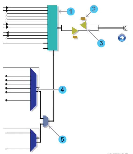
Consider the exhibit which shows part of an EPT Schematic View. Which number refers to the Wavelength Router (WR8-88) block?

Correct Answer: A. 1
Explanation:

The Wavelength Router (WR8-88) block is a device that can route optical signals based on their wavelengths. It can also perform wavelength conversion, multiplexing, and demultiplexing functions.The Wavelength Router (WR8-88) block is part of the Nokia 1830 PSS-8x platform, which is optimized for metro aggregation switching applications in optical transport networks1. In the exhibit, the number 1 refers to the Wavelength Router (WR8-88) block, as indicated by the label WR8-88AF. The other numbers refer to different components of the system, such as transponders, amplifiers, and switches.Reference:Nokia Optical Diagnostics and Troubleshooting Course,DWDM 1830 PSS-8 WR8-88AF Board


Question 3

Suppose a channel-related alarm is reported on an 1830 PSS node, and is related to a possible Wave Keys clock source issue. What is the recommended order for the following troubleshooting steps?

Correct Answer: A. 1. Retrieve the channel power trace. 2. Determine the active clock reference source. 3. Switch to alternate clock source (PF). 4. Replace the suspect PF.
Explanation:

The recommended order for the troubleshooting steps is A, as follows:

Retrieve the channel power trace.This step is useful to identify the affected channel and its power level, as well as to check if there are any fluctuations or anomalies in the power trace that could indicate a clock source issue1.

Determine the active clock reference source. This step is necessary to verify which clock source is currently used by the node, and if it matches the expected configuration.The clock source can be either a local oscillator (LO) or a phase-locked loop (PLL) that synchronizes with an external reference2.The active clock source can be determined by using the commandshow interface ot 1/1/lineout detail3.

Switch to alternate clock source (PF). This step is helpful to isolate the problem and confirm if the suspect PF is indeed causing the channel-related alarm.By switching to an alternate clock source, such as another PF or an external reference, the node can recover from the alarm if the original clock source was faulty4.

Replace the suspect PF. This step is the final solution to resolve the issue and restore the normal operation of the node.The suspect PF should be replaced with a new one that has the same specifications and configuration as the original one5.Reference:Nokia Optical Diagnostics and Troubleshooting Course | Nokia,Optical User Guide - Nokia,Alcatel-Lucent 1830 PSS-8 and PSS-16 Photonic Service Switch


Question 4

Suppose a unidirectional amplifier has been plugged into slot 1/13. Which command should the user enter to retrieve the OSC pluggable module type?

Correct Answer: D. show interface 1/13/OSCSFP detail
Explanation:

The command that the user should enter to retrieve the OSC pluggable module type isshow interface 1/13/OSCSFP detail. This command will display detailed information about the OSC interface on slot 1/13, including the type of pluggable module that is installed in it. The pluggable module type can be either SFP or SFP+, depending on the speed and distance requirements of the OSC link. The command will also show other parameters, such as wavelength, frequency, transmit power, receive power, and status. The other commands are incorrect because they either do not show the pluggable module type or have invalid syntax.Reference:Nokia Optical Diagnostics and Troubleshooting Course,OSFP OCTAL SMALL FORM FACTOR PLUGGABLE MODULE


Question 5

Which of the following statements about optical power vs amplification stages is TRUE?

Correct Answer: C. When multiple channels pass through a shared port (for example, an amplifier line interface), the total aggregated power reflects the number of channels currently present.
Explanation:

The statement that when multiple channels pass through a shared port (for example, an amplifier line interface), the total aggregated power reflects the number of channels currently present is TRUE. This means that the more channels are present, the higher the total output power will be, and vice versa.This is because each channel contributes to the total power by its own power level, and the amplifier tries to maintain a constant gain for each channel2.Therefore, the total output power depends on both the input power and the number of channels3.Reference:Nokia Optical Diagnostics and Troubleshooting Course | Nokia,Optical amplifiers, explained by RP; optical amplification,Amplifier chains, explained by RP; amplifier stages, preamplifier ...


Question 6

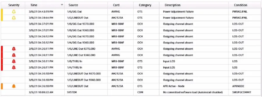
Refer to the exhibit, which shows a conditions list from the 1830 PSS GUI. (i) What is the total number of alarms reported? (ii) How many service affecting alarms are displayed? (iii) How many conditions are displayed?

Correct Answer: B. (i) total number of alarms = 7 (ii) number of service affecting alarms = 5 (Hi) number of conditions = 7
Explanation:

The exhibit shows a conditions list from the 1830 PSS GUI, which displays the alarms and events that occur on the network elements. The total number of alarms reported is equal to the number of rows that have a red or yellow icon in the Severity column, indicating a critical or major alarm. In this case, there are 7 rows with such icons, so the total number of alarms is 7. The number of service affecting alarms is equal to the number of rows that have a ''Yes'' value in the Service Affecting column, indicating that the alarm affects the service quality or availability. In this case, there are 5 rows with such values, so the number of service affecting alarms is 5. The number of conditions is equal to the total number of rows in the table, regardless of their severity or service affecting status. In this case, there are 7 rows in the table, so the number of conditions is 7.Reference:Optical User Guide - Nokia,Security Target Nokia 1830 Photonic Service Switch (PSS)